Hyundai Tucson: Engine And Transaxle Assembly / Engine And Transaxle Assembly Repair procedures
| Removal |
|

|

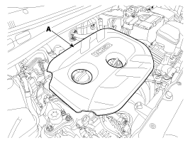
| 1. |
Remove the engine cover (A).
|
| 2. |
Disconnect the battery terminals (A). The negative terminal first.
|
| 3. |
Remove the air cleaner assembly.
|


| 4. |
Remove the battery (A) after removing the mounting bracket (B).
|

| 5. |
Disconnect the ECM connectors (A) and remove the ECM (B).
|

| 6. |
Loosen the battery “+” cable bracket mounting bolt (A) and then remove the battery tray (B).
|

| 7. |
Remove the under cover (A).
|

| 8. |
Loosen the drain plug, and drain the engine coolant. Remove the radiator cap to help drain the coolant faster.
(Refer to Cooling system in this group) |
| 9. |
Disconnect the radiator upper hose (A).
|

| 10. |
Disconnect the radiator lower hose (A).
|

| 11. |
Recover the refrigerant and then remove the high pressure pipe and the low pressure pipe (A).
(Refer to Heating,Ventilation, Air Conditioning - "Air Conditioning System")
|

| 12. |
Remove the transaxle wire harness connectors, control cable and hoses from the transaxle.
(Refer to Manual Transaxle System)
(Refer to Automatic Transaxle System) |
| 13. |
Disconnect the heater hoses (A).
|


| 14. |
Disconnect the wiring connectors and harness clamps, and then
remove the wiring and protectors from the cylinder head and the intake
manifold.
|


| 15. |
Disconnect the "+" cable (A) and the front connector (B).
|

| 16. |
Disconnect the fuel hose (A) and the PCSV (Purge control solenoid valve) hose (B).
|

| 17. |
Remove the front muffler ( A).
|

| 18. |
Remove the steering u-joint mounting bolt (A).
(Refer to Steering System - “Steering Gear Box”)
|

| 19. |
Remove the front wheels.
(Refer to Suspension System) |
| 20. |
Remove the lower arms (A).
(Refer to Suspension System - “Front Lower Arm”)
|

| 21. |
Remove the stabilizer bar links (A).
(Refer to Suspension System - “Front Stabilizer Bar”)
|

| 22. |
Remove the tie rod ends (A).
(Refer to Steering System - “Steering Gear Box”)
|

| 23. |
Disconnect the drive shafts (A) from the axle hubs.
(Refer to Driveshaft and axle - “Front Driveshaft”)
|

| 24. |
Remove the roll rod bracket (A).
|

| 25. |
Remove the roll rod mounting support bracket (A).
|

| 26. |
Support the sub frame (A) with a floor jack, and then remove the sub frame mounting bolts and nuts.
|

| 27. |
Disconnect the ground line (A), and then remove the engine mounting support bracket (B).
|

| 28. |
Disconnect the ground line (A).
|

| 29. |
Remove the service cover (A).
|

| 30. |
Remove the transaxle mounting bracket bolt (A).
|

| 31. |
Lower the engine and transaxle assembly (A) using a floor
jack and then remove the engine and transaxle assembly by lifting
vehicle.
|

| Installation |
Perform the following:
|
 Engine Mounting Components and Components Location
Components
1. Engine mounting bracket2. Transaxle mounting bracket3. Roll rod bracket
...
 Timing System
...
Other information:
Hyundai Tucson (LM) 2010-2015 Service Manual: Description and Operation
Description
The starting system includes the battery, starter, solenoid
switch, ignition switch, inhibitor switch (A/T), clutch pedal switch
(M/T), ignition lock switch, connection wires and the battery cable.
When the ignition key is turned to the start position, current flows and energizes ...
Hyundai Tucson (LM) 2010-2015 Owners Manual: To set cruise control speed
1.Push the cruise ON/OFF button on the steering wheel to turn the system on.
The CRUISE indicator will illuminate.
2.Accelerate to the desired speed, which must be more than 25 mph (40 km/h).
3.Push the lever (1) down (to SET-) , and release it. The SET indicator light
will illuminate. ...